Conversions: Design the Assist System
Pairing aerodynamic efficiency with modest, torque-sensed electric assistance creates one of the lowest-energy personal vehicles ever built. Success depends on treating motor torque, battery mounting, braking heat, and cell protection as a unified system rather than bolted-on accessories.
Matching Motor Topology to Aerodynamic Load
Streamlined bicycles carry weight penalties uphill where gravity dominates, yet need very little power to hold 25 km/h on the flat. Selecting between a bottom-bracket mid-drive, an internally geared hub motor, and a direct-drive hub motor determines how efficiently copper windings convert amp-hours into forward climb without overheating on 10% gradients.
Mid-drive units (such as torque-sensing Tongsheng TSDZ2 or Bafang BBS architectures tuned to legal continuous limits) work through the bicycle’s rear cassette, keeping motor RPM near its 78%–82% efficiency plateau on steep ascents while centralizing mass low at the bottom bracket shell. Direct-drive hubs add unsprung rear wheel mass and slight cogging drag when coasting, yet enable smooth regenerative braking on long descents—saving brake pads on heavier faired prototypes.
Limiting controller phase current and combining a 250 W torque-sensing mid-drive with an aerodynamic frame bag and rear wheel cover extends real-world range per Wh by over 20%.
Logged via an inline shunt watt-hour meter (such as a Cycle Analyst V3): consumption drops from 11.4 Wh/km upright to 8.6 Wh/km on mixed rural tarmac.
Evaluating Conversion Topologies & Regulatory Envelopes
Before ordering components, establish whether your prototype will operate on public highways and cycle tracks. Under UK EAPC regulations and European standard BS EN 15194, pedal-assist cycles must require pedalling to activate assistance, cut motor output smoothly by 25 km/h (15.5 mph), and carry a motor rated at no more than 250 W continuous output. Exceeding those thresholds reclassifies the machine as a motor vehicle requiring type approval, registration, insurance, and motorcycle protective gear.
| Drive Type | Mass Placement | Drivetrain Wear | Dropout / Frame Stress | Regenerative Braking |
|---|---|---|---|---|
| Torque-Sensing Mid-Drive | Central & low at crankset | Higher chain & sprocket load; requires shift discipline | Rotational reaction against down tube | No (freewheels at crank) |
| Geared Rear Hub Motor | Rear wheel (~2.8–3.4 kg) | Independent of chain; works even if chain snaps | Moderate axle reaction; requires torque arm on alloy frames | Rare (internal clutch freewheels) |
| Direct-Drive Rear Hub | Heavy unsprung rear (~5.5 kg) | Zero extra chain wear | Reversing regen + drive torque; dual torque arms mandatory | Yes; recovers 5%–10% in hilly terrain & spares rims |
Axle Torque Reactions, Rivnuts, and Cell Stewardship
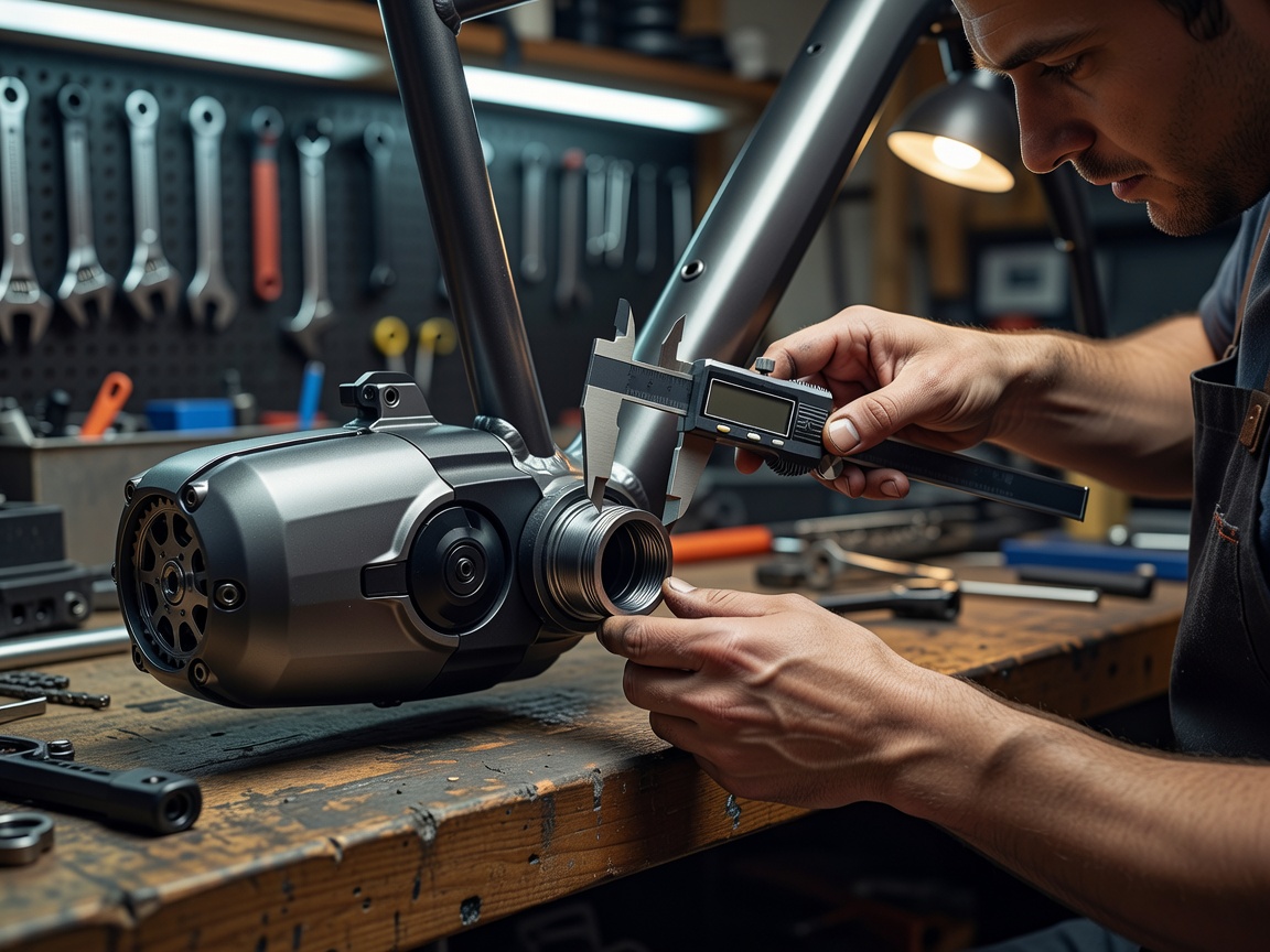
Standard bicycle dropouts are slotted to hold a round 10 mm axle in compression, not to resist 40 Nm of twisting reaction across two 10 mm flats. Installing any hub motor into aluminium or carbon forks is a classic failure mode: the flats pry open the dropout jaws within hundreds of kilometres. Always anchor laser-cut 4 mm 304 stainless steel torque arms to a frame eyelet or broadband hose-clamp clevis on steel or rear alloy stays—and never mount hub motors in carbon or suspension front forks.
Equally critical is battery mounting. Two standard M5 water-bottle rivnuts pressed into a 0.9 mm down tube were engineered for a 750 g bidon, not a 3.6 kg lithium-ion pack vibrating over cattle grids. Distribute battery cradle loads through full-perimeter padded frame straps or a CNC triple-bobbin rail spanning at least three fastening points.
Electrical & Braking Inspection Protocol
- Certified cells & BMS: Use packs assembled from traceable tier-one cells (Samsung, Panasonic, Molicel, LG) managed by a temperature-monitored Battery Management System certified to UL 2271 or EN 50604-1.
- Fusing & connectors: Fit an appropriately rated DC blade or MIDI fuse close to the positive discharge terminal and use anti-spark XT90-S or Anderson Powerpole connectors with heat-shrink strain relief.
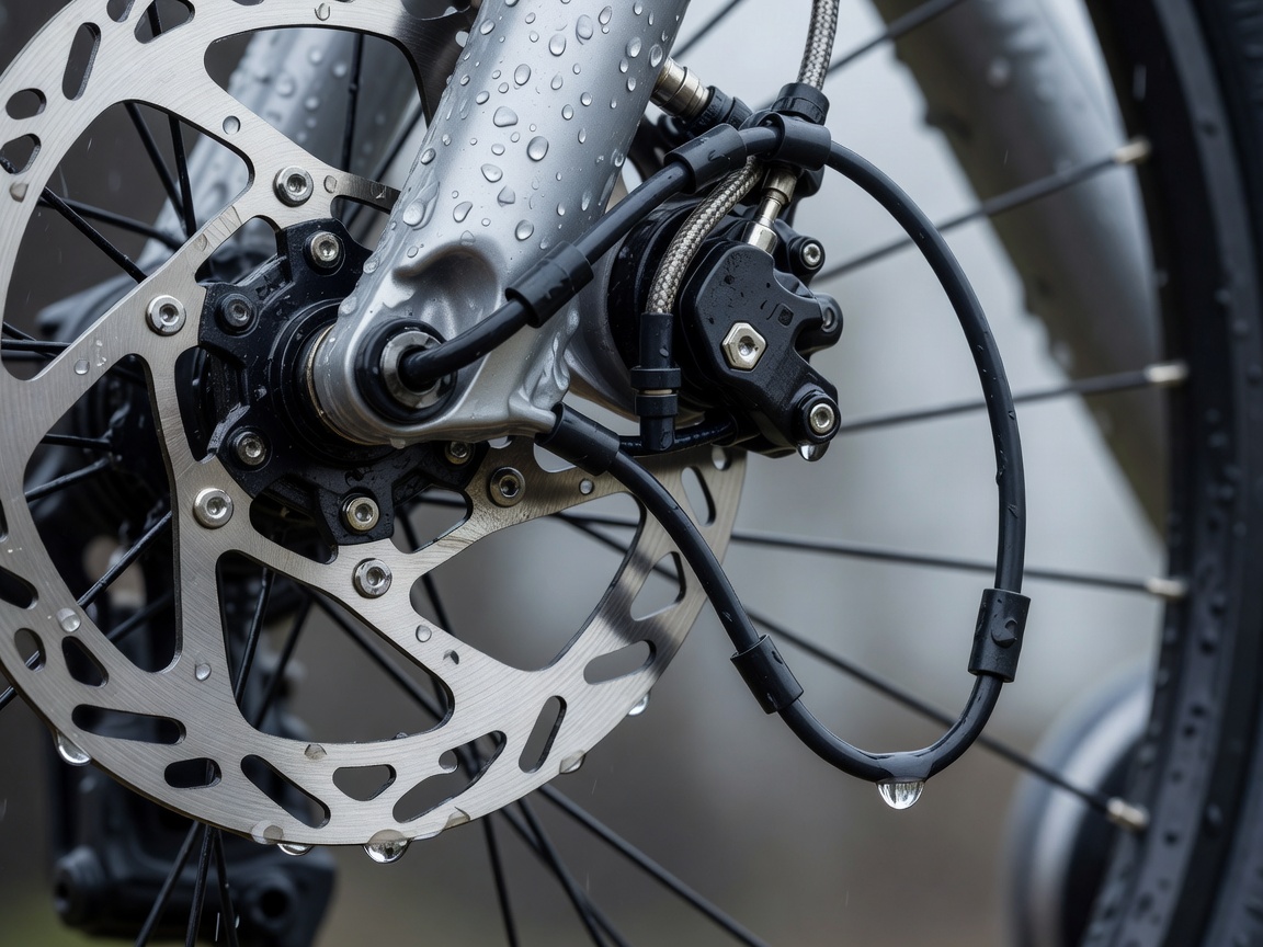
- Upgraded stopping thermal capacity: Step up to 180 mm or 203 mm hydraulic disc rotors with sintered or semi-metallic pads when total system mass increases by more than 6 kg.
- Drip loops & grommets: Form downward cable drip loops below controller entries so rainwater runs off rather than wicking along harness sheathing into connectors.