Aerodynamics: Let the Air Set the Questions
Rocket nose cones pierce supersonic shockwaves, whereas a cyclist moves through sea-level air at Reynolds numbers between 100,000 and 800,000. At cycling speeds, a blunt, rounded leading edge paired with a gently tapered trailing fairing saves far more wattage than a needle-sharp prow.
Start Behind the Saddle, Not Ahead of the Front Hub
When tinkerers sketch their first rocket-inspired bicycle, intuition usually places a sweeping bullet nose over the handlebars. Yet as Chester Kyle and David Gordon Wilson documented in Bicycling Science, roughly 70% to 80% of pressure drag on an upright cyclist comes from the low-pressure turbulent wake detaching behind the rider’s torso, hips, and spinning rear spokes.
More importantly, adding lateral surface area forward of the front contact patch moves the aerodynamic centre of pressure ahead of the steering axis. When a sudden crosswind gust strikes from a 15-degree yaw angle, a front-heavy fairing acts like a weathervane facing backward—actively trying to twist the front wheel away from the wind. A responsible first modification therefore leaves the front wheel unobstructed and focuses on a lightweight rear tailbox, frame-triangle infill panel, or removable rear wheel disc cover.
A Coroplast or thin birch-ply rear tailbox extending 450 mm aft of the rider’s lower back reduces wake suction while shifting lateral area rearward for calmer crosswind stability.
Typical commuter CdA drops from ~0.36 m² to ~0.31 m² at 30 km/h—saving approximately 22 watts on flat tarmac while adding only 1.1 kg of static mass.
Kamm-Tail Truncation and Centre of Pressure Balance
Full 4:1 fineness-ratio teardrops recommended by classic NACA subsonic tables become impractically long behind a bicycle, catching garage doorways and adding unnecessary skin-friction surface area. Following Wunibald Kamm’s 1930s automotive research—later adapted to UCI-style truncated-foil frame tubes—cutting off the rear third of a teardrop at roughly 50% of its maximum width preserves most of the pressure recovery because the stagnant wake forms a "virtual tail."
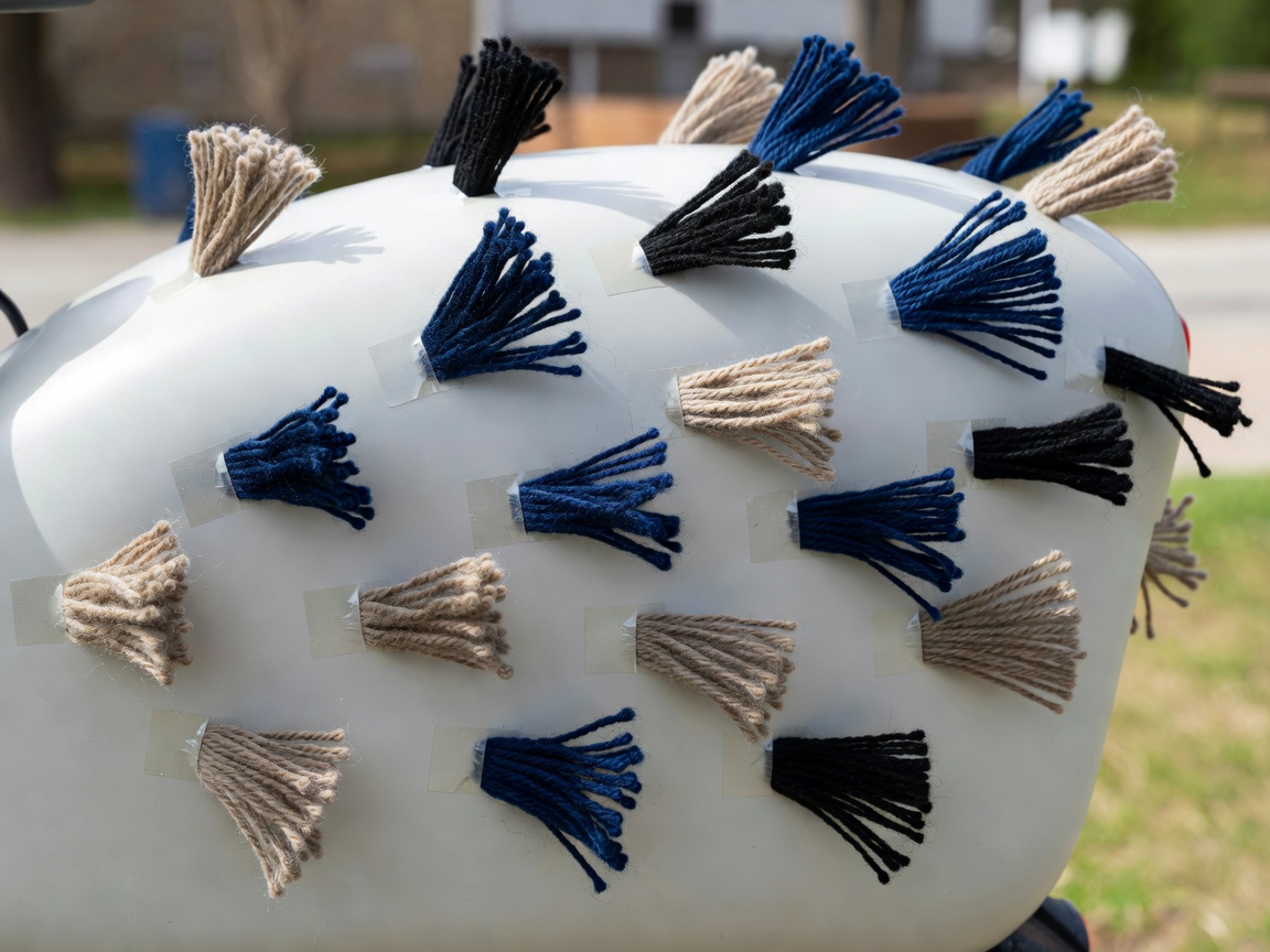
Workshop Rule of Thumb: Keep the geometric centroid of projected side area at or behind the midpoint of the wheelbase. Before testing outdoors, hang the completed bicycle horizontally from a single ceiling cord at its centre of gravity and hold a workshop box fan at 30 degrees off-axis to observe which way the nose rotates.
| Configuration | Typical CdA (m²) | Power for 32 km/h (Flat, Calm) | Crosswind Sensitivity |
|---|---|---|---|
| Upright Utility Bike (Loose Jacket) | 0.40 – 0.44 | ~215 W | Low, predictable buffeting |
| Road Position + Narrow Bars + Frame Pack | 0.30 – 0.33 | ~168 W | Very manageable |
| Upright + Rear Tailbox + Rear Wheel Cover | 0.26 – 0.29 | ~148 W | Weathervane-stable; slight rear push |
| Fully Faired Recumbent Velomobile (Reference) | 0.06 – 0.09 | ~65 W | Requires careful body profile & three tracks or practiced rider |
Measuring Real Drag Without a Wind Tunnel
Wind tunnel time at facilities such as the Silverstone Sports Engineering Hub costs hundreds of pounds per hour, yet Robert Chung’s Virtual Elevation method lets patient home builders detect 0.01 m² changes in CdA on a quiet cul-de-sac or gentle hill at dawn.
By riding the exact same loop repeatedly at alternating speeds (for example, 18 km/h on lap one and 34 km/h on lap two) while recording accurate wheel speed via a reed switch and crank power, software such as GoldenCheetah’s Aerolab reconstructs the road elevation profile. Only one combination of rolling resistance (Crr) and drag area (CdA) makes the start and finish elevations match across slow and fast laps.
Fairing Fabrication & Fitment Checklist
- Edge protection: Trim all sheet aluminium, polycarbonate, or fibreglass edges with split rubber U-channel edging (minimum 4 mm radius) so no bare edge can contact the rider in a spill.
- Steering sweep clearance: Check full 45-degree handlebar rotation while compressing the front fork to bottom-out travel.
- Ventilation & demisting: Provide NACA-style flush intake ducts and high-point exhaust vents if using any transparent windscreen to prevent fogging and heat exhaustion.
- Breakaway fasteners: Mount non-structural fairings with nylon M5 shear bolts or rubber isolation bobbins rather than rigid steel clamps onto thin-walled frame tubes.